
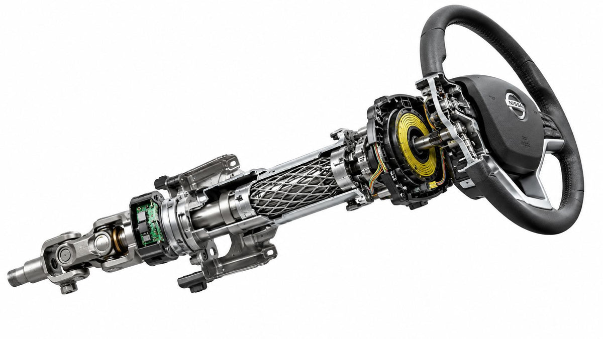
Most explanations of what is the steering column start and finish with “the shaft behind the steering wheel.” That answer is incomplete, and after a collision it can be dangerous. The modern steering column is a mechanical torque path, a controlled crash structure, an airbag interface, a sensor carrier, and sometimes a shift-control assembly. The wheel can still turn while one of those safety functions has already been compromised.
A post-crash vehicle therefore needs more than a steering test. The correct question is whether the mechanical integrity, restraint-system alignment, clockspring position, wiring, modules, and calibration still meet the manufacturer's repair procedure. Treating the column as ordinary trim or replacing the complete assembly without diagnosis can both produce a poor repair outcome.
Table of Contents
- Redefining the Modern Steering Column
- Core Mechanical and Electronic Components
- The Engineering Shift to Energy Absorption
- Diagnosing Electronic and Control Module Faults
- Post-Collision Inspection and Hidden Damage
- Traditional Mechanics Versus Steer-by-Wire
- Executing a Complete Safety System Restoration
Redefining the Modern Steering Column
A steering column is no longer just the shaft behind the steering wheel. It is a structural load path, a controlled crash component, an airbag interface, and an electronic hub connecting the driver to several vehicle systems. Depending on the vehicle, the assembly may house the driver airbag, clockspring, steering-angle sensor, steering-column control module, ignition or start hardware, wheel switches, and a column-mounted gear selector.
That concentration of functions changes how technicians should diagnose damage. A fault near the wheel can affect airbag communication, electronic stability control, steering-wheel buttons, shift-position information, or calibration data. Shared wiring, connectors, and control logic allow one damaged area to produce symptoms in systems that seem unrelated.
Practical rule: A steering wheel that turns proves only that some torque reaches the steering gear. It says nothing about correct crash collapse, sensor accuracy, or restraint-system operation.
Why the simple definition fails
The traditional definition covers only steering transmission. Modern columns perform three separate jobs:
- Steering transmission: The shaft and intermediate joints carry torque to the rack or gearbox while accommodating changes in angle and vehicle packaging.
- Occupant protection: Collapsible sections, shear capsules, mounts, and energy-absorbing structures control steering-wheel movement during a frontal impact.
- Vehicle control and restraint communication: Sensors and modules report steering position, torque, switch activity, and other information to vehicle networks and safety controllers.
Those functions can fail separately. The column may feel normal while the steering-angle sensor has lost calibration. The housing may show no obvious bend even though a telescoping section has absorbed crash energy. Steering may remain available while an internal module fault disables an electronic safety function.
A 2026 NHTSA recall report involving certain Ram 2500 vehicles shows why a mechanical steering check is insufficient. An internal steering-column control-module fault could disable electronic stability control and illuminate the ESC warning light without producing an obvious steering symptom. A separate recall involving a column-mounted shifter demonstrates another failure mode. Mechanical detachment could prevent selection of Park and create a rollaway hazard.
The post-crash implication
Begin inspection by separating the failed function from the assembly that contains it. Check for mechanical deformation, altered collapse position, clockspring indexing, damaged wiring, module faults, sensor calibration errors, and restraint-system communication problems. The repair may require a sensor, clockspring, harness, control module, calibration procedure, or mechanical column component rather than automatic replacement of the complete assembly.
The column belongs in the same safety assessment as the airbag module and seat belts. Its position or deformation can affect airbag alignment, driver protection, and the wider supplemental restraint system. Rebuilders should check the vehicle identification number in the NHTSA recall database before buying parts or beginning column-area work, then follow the manufacturer's inspection and calibration procedures.
Core Mechanical and Electronic Components
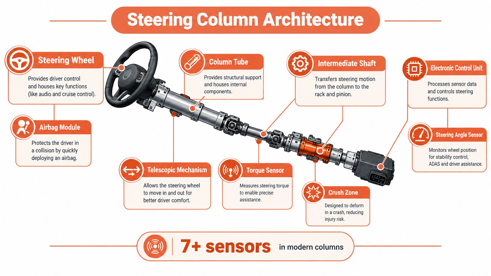
The mechanical side is easiest to understand as a torque path. The driver turns the steering wheel, the steering shaft carries that rotation through the column tube, and the intermediate shaft transfers it to the steering rack or gearbox. Universal joints allow the shafts to work through changing angles created by the instrument panel, footwell, engine-bay packaging, and steering gear location.
The column tube supports bearings, adjustment hardware, and crash-management components. In an adjustable column, telescoping and tilt mechanisms let the wheel move to the driver's preferred position without losing the required structural support. A collapsible section remains rigid enough for normal steering but is designed to move under defined crash loading.
Following the torque path
A typical universal joint uses two yokes, a cross shaft, and four needle bearings to transmit steering torque despite angular differences between the steering wheel and steering rack, as described in this technical review of steering-column construction. Those small bearings matter. Wear or seizure can create clunking, excess free play, uneven steering effort, or a delay between wheel movement and rack response.
A useful inspection sequence is:
- Hold the steering wheel stationary and inspect downstream movement. Look for movement at the column mounts, intermediate shaft, and universal joints before assuming the rack has failed.
- Check for binding through the steering range. A joint that feels smooth in one position can tighten at another angle.
- Inspect bearings and joint condition. Rust, looseness, impact marks, or abnormal resistance can point to a joint or intermediate-shaft problem.
- Verify telescoping and tilt operation. The adjustment mechanism should move as designed and lock securely. Don't force a mechanism that was loaded in a crash.
- Check mounting hardware. Loose brackets can mimic shaft play and can alter the column's crash behavior.
On electronically assisted systems, the column may also contain a torsion bar, steering-torque sensor, steering-position sensor, electric motor, reduction gear, and control electronics. The torsion bar twists slightly as the driver applies steering effort. The torque sensor measures that change, while the controller uses the signal to command electric assistance. A steering-angle sensor provides position information used by systems such as stability control and driver-assistance functions.
Symptoms that point to different faults
Clunking during a small steering correction often deserves a mechanical inspection of the universal joints, intermediate-shaft bearings, and mounting points. Inconsistent assistance or a sudden change in steering effort points more toward the electric motor, torque sensor, power supply, or control electronics, although mechanical binding must be ruled out first.
A diagnostic scan should complement physical inspection, not replace it. A code can identify a communication or calibration problem, but it can't confirm that a shaft is straight, a joint is free, or a collapse mechanism remains unused.
The most effective repair approach is component-level triage. Replace the complete column only when the manufacturer procedure, measured damage, or failed integrated parts justify it. A noisy bearing, damaged intermediate shaft, failed sensor, or wiring fault may not require the same remedy as a deformed column assembly.
The Engineering Shift to Energy Absorption
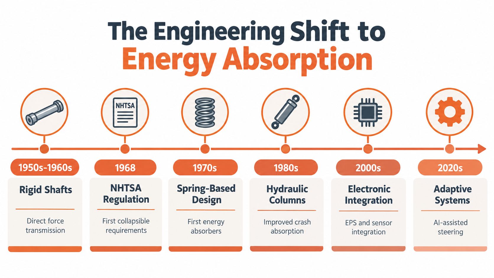
A steering column must resist driver input in normal use and yield in a controlled crash. Early rigid columns created a direct load path from the steering wheel to the driver. That stiffness transmitted steering effort, but it could also transfer crash forces and rearward wheel movement into the occupant compartment. Engineers separated those two behaviors by adding structures designed to deform under defined loads.
Mercedes-Benz introduced a telescoping safety column with an impact absorber in 1959 and made safety steering standard across its passenger-car range in 1967. General Motors introduced an energy-absorbing steering column in 1967. Its two-piece construction used crushable steel mesh and allowed the column to retract by as much as 8.25 inches during a severe frontal collision, according to General Motors' history of automotive safety developments.
Controlled deformation is intentional
The United States introduced Federal Motor Vehicle Safety Standard 204 in the late 1960s to limit rearward steering-wheel movement during crashes. NHTSA's performance-based standards do not prescribe one collapsible-column design. A manufacturer may combine column collapse, an energy-absorbing steering wheel, and other mechanisms to meet the required performance, as explained in the NHTSA interpretation of steering-column safety requirements.
That distinction changes the inspection decision. A column that has moved, telescoped, or crushed may have performed its crash function rather than failed as a rigid component. It still cannot return to service because it looks straight from the driver's seat. Verify remaining travel, mounting points, universal joints, restraint interfaces, and the manufacturer's replacement criteria. A damaged collapse zone can alter occupant protection even when steering effort and wheel alignment appear normal.
The engineering trade-off was measurable. A technical review reported that the average passenger-car steering-column assembly weighed 9.94 pounds in 1966 and 11.90 pounds in 1983, an increase of 1.96 pounds, or approximately 19.7%, as energy-absorbing systems became established. The added mass represented crushable structures, telescoping interfaces, energy absorbers, and stronger mounting arrangements, as detailed in this review of automotive safety milestones.
Why the added complexity matters
The same review states that federal statistics attributed approximately 53,000 prevented deaths to energy-absorbing steering columns between their introduction in 1968 and 2002. That history supports a practical repair rule: inspect the column as part of the occupant-protection system, not as an ordinary shaft or linkage.
A column is designed to be stiff during steering and compliant during a defined crash event. Crush zones, telescoping sections, shear capsules, mounts, and energy absorbers manage that change. Each part has a different failure mode, so replacing only the visibly damaged item can leave a compromised crash path behind.
Post-crash triage should include the steering wheel, column mounts, intermediate shaft, SRS interfaces, and belt restraint system. Check the seat belt pretensioner system alongside the column, because belt retraction and steering-wheel movement jointly control occupant position. A replacement part must steer correctly and retain the specified collapse characteristics. Anything less is an incomplete safety-system restoration.
Diagnosing Electronic and Control Module Faults
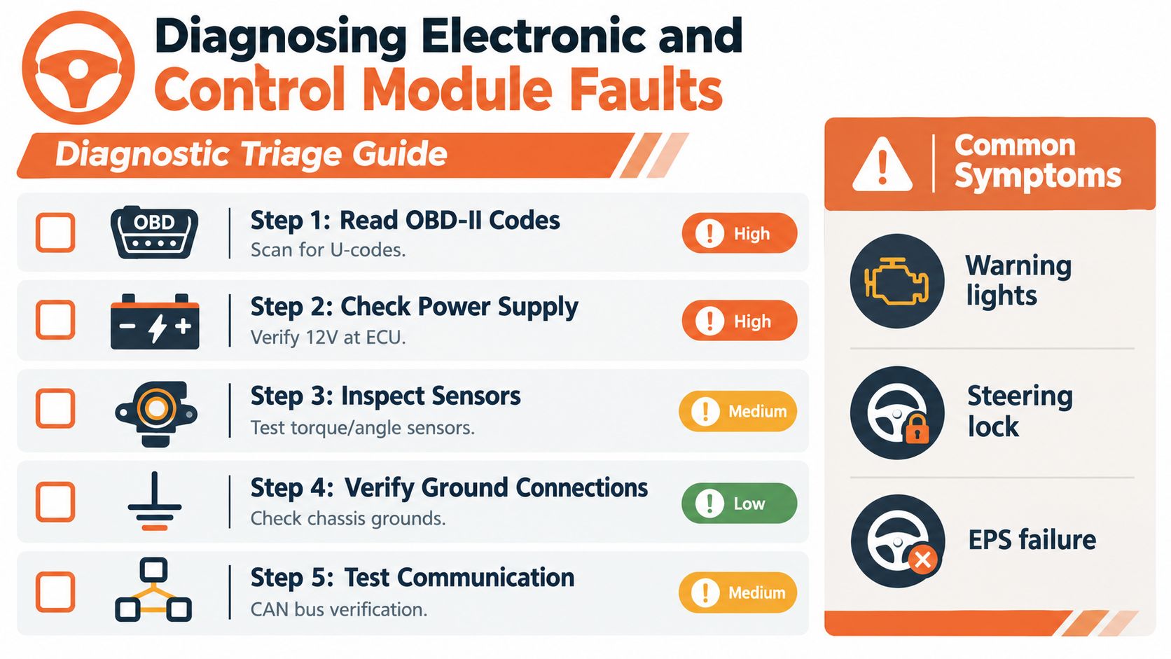
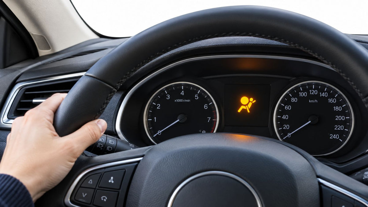
A steering column can steer normally while its electronics create a safety fault. Warning lights often point owners toward the wrong system. An ESC warning may resemble a brake or wheel-speed problem, an airbag warning may be mistaken for a seat fault, and lost steering-wheel controls may appear to indicate a failed switch. Because the column houses sensors, clocksprings, modules, and wiring, one local failure can interrupt several vehicle functions.
Use the 2026 Ram 2500 recall as a triage cue, not as a reason to replace the column. If ESC is disabled without a clear mechanical steering symptom, check module communication, power, and grounds before inspecting shafts and joints. That order helps separate an electronic control fault from physical damage.
Separate mechanical from electronic symptoms
Begin with the driver's complaint and divide the diagnosis into two paths.
Mechanical indicators include looseness, abnormal free play, binding, uneven effort, a clunk through the shaft, or a steering wheel that fails to return normally. Inspect the shaft, joints, bearings, column mounts, and steering gear by hand.
Electronic indicators include warning lights, lost steering-wheel controls, an implausible steering-angle reading, intermittent communication faults, an inoperative column shifter, or assistance that disappears without physical binding. These symptoms call for a scan tool, power and ground tests, network checks, and calibration verification.
Use this diagnostic sequence:
- Read all relevant modules. Scan the chassis, restraint, steering, and body modules, not only the engine controller. Record communication codes before clearing anything.
- Verify power and grounds. Low voltage or a poor ground can imitate several module failures.
- Inspect the clockspring and connectors. Check centering, connector locks, harness routing, impact evidence, and signs of careless prior work.
- Test sensor plausibility. Compare steering-angle and torque readings with the wheel centered, then while turning slowly.
- Check calibration requirements. A replaced or disturbed sensor may require a manufacturer-specific zero-point or steering-angle procedure.
- Confirm recall status. A safety-related module fault may have a remedy different from ordinary parts replacement.
Don't probe restraint wiring casually
The clockspring carries circuits between the stationary column and rotating steering wheel. It commonly serves the driver airbag and steering-wheel controls, so incorrect centering or probing can create a restraint fault. Follow the correct service information, isolation procedure, and equipment requirements before working near airbag or pretensioner circuits.
Treat the column-mounted shifter with the same caution. If the lever detaches, moves without changing transmission position, or fails to indicate Park clearly, stop using the vehicle until the mechanism and position feedback have been inspected. Identify the failed module, switch, wiring, mechanical interface, or recall remedy before replacing column components.
For related restraint-module diagnosis, consult this restraint control module service guide, then apply the vehicle manufacturer's instructions for the specific platform.
Post-Collision Inspection and Hidden Damage
A steering column can feel normal after a frontal collision and still be unsafe. Treat any impact involving wheel movement or airbag deployment as a potential energy-management event until the column has been measured against manufacturer specifications. Internal telescoping sections may have compressed, a shear capsule may have released, a mounting bracket may have shifted, or a universal joint may have changed position without obvious damage from the driver's seat.
Under NHTSA's performance-based approach to FMVSS 204 noted earlier, acceptable crash performance can involve several structural features working together. That means normal steering feel does not prove that the column's collapse features remain serviceable.
A three-point inspection
1. Establish the crash path. Identify the impact location, the direction and extent of steering-wheel or column movement, and whether the driver airbag deployed. Inspect the column tube, lower and intermediate shafts, universal joints, mounts, tilt and telescope mechanisms, and nearby instrument-panel structure. Fresh witness marks, displaced brackets, distorted fasteners, cracked plastic, and an abnormal shaft angle can reveal movement that a basic steering check misses.
2. Verify energy-management components. Do not approve a collapsible column by appearance alone. Measure the relevant dimensions against manufacturer specifications, inspect for compressed or released sections, and determine whether shear capsules, pyrotechnic devices, or detachable mounts operated. If service information requires replacement after a collision or deployment, visual inspection cannot replace that procedure.
3. Connect the column findings to the SRS inspection. Examine the driver airbag, clockspring, steering-angle sensor, column wiring, SRS module, seat belt pretensioners, and crash sensors as one affected system. A displaced column can change airbag alignment. Deployment can leave crash data or hard codes in the SRS module. A seat belt may stay locked or fail to retract even after the column appears repaired.
What not to do
Do not straighten a bent column, weld a crash member, bypass an airbag connector, or install a used assembly because the wheel turns. A used part may contain hidden crash damage, and an off-center clockspring can fail when the wheel rotates. Clearing codes with a generic tool can remove a warning without restoring the required function.
A vehicle is not ready because it starts, steers, and shows no warning light after a battery reset. Release it only after the affected safety systems pass the specified inspection, repair, and calibration checks.
Before disassembly, record original codes, part numbers, deployment history, and measured findings. Photograph connector routing and mounting positions. For the wider repair sequence, consult this collision damage repair guidance, then use the vehicle's service documentation for final decisions.
Traditional Mechanics Versus Steer-by-Wire
Traditional steering gives a technician something tangible to inspect. The steering wheel connects through shafts and joints to the rack, so looseness, impact damage, binding, and deformation can often be located with a careful physical examination. Its safety challenge is preserving torque transmission during normal driving while allowing controlled movement in a crash.
Steer-by-wire removes the direct mechanical shaft between the steering wheel and road wheels. The wheel becomes an input device, and electronic commands travel to steering actuators. That can support different packaging and variable steering-ratio strategies, but it doesn't make the safety problem smaller. It changes the failure modes.
What replaces the physical column function
Without a direct shaft, there is no conventional column to absorb crash energy in the same way. Occupant protection must come from the steering-wheel assembly, instrument-panel structure, restraint systems, and other vehicle structures. Steering availability, meanwhile, depends on fail-operational design, redundant actuators, parallel control paths, and independent power routes.
Engineering discussions of steer-by-wire emphasize redundant steering architecture and fault-tolerant operation. The system must continue providing steering after a single electronic fault, which shifts inspection from visible shaft condition toward power supply integrity, communications, software behavior, actuator health, and fault handling.
| Conventional column | Steer-by-wire |
|---|---|
| Inspect shafts, joints, mounts, and collapse sections | Verify actuators, power routes, networks, and fault responses |
| Damage may leave physical witness marks or play | A serious fault may have little visible evidence |
| Mechanical alignment and sensor calibration both matter | Redundancy and software calibration become central |
| Crash deformation can compromise restraint alignment | Electronic failure management becomes a primary safety function |
For salvage and repair work, the lesson is not that one design is automatically safer. A conventional column can look straight while its collapse mechanism or clockspring is damaged. A steer-by-wire system can look undamaged while a redundant path, power supply, or controller has failed. In both cases, the vehicle needs mechanical, restraint-system, and electronic verification before return to service.
Executing a Complete Safety System Restoration
A steering-column repair is only complete when the surrounding safety system has been restored. The final inspection should include the column structure and mounts, airbag and clockspring interfaces, steering-angle data, SRS module status, seat belt pretensioners, belt webbing, connectors, and manufacturer-required calibrations.
The repair order matters. Identify the collision history and diagnostic codes first. Then inspect or replace compromised hardware, restore the SRS module according to the correct procedure, repair or replace locked pretensioners, address deployed gas generators and airbags, and complete the required scan and calibration checks. Cheap, uncertified parts can create fitment, compatibility, and crash-performance problems that aren't visible during a short road test.
A complete restoration also leaves an audit trail. Keep the scan report, photographs, part numbers, repair records, and calibration results with the vehicle file. That documentation helps another technician understand what changed and prevents a future owner from mistaking a cleared warning light for a verified repair.
If you're rebuilding a collision vehicle, send damaged seat belts, pretensioners, and SRS modules to Seat Belt Repair for mail-in service using OEM components, then reinstall them through a qualified local repair facility and complete the vehicle-specific final checks. Their services address pretensioner repair, webbing replacement, and SRS module reset, giving your column inspection a properly restored restraint-system foundation.

Leave a comment
This site is protected by hCaptcha and the hCaptcha Privacy Policy and Terms of Service apply.