
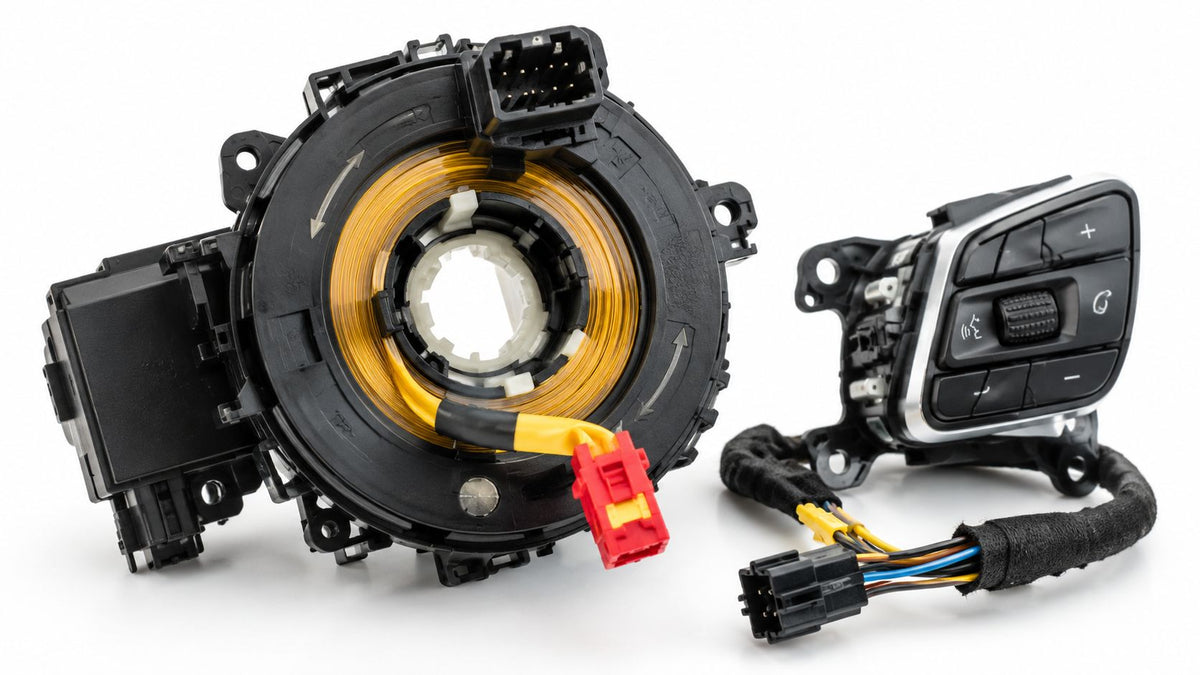
You turn the steering wheel after a repair and notice the airbag light is still on. The horn may be silent, the audio buttons may have stopped responding, or a faint clicking sound may come from behind the wheel. It's tempting to replace the most obvious part and move on, but these symptoms don't prove that the clock spring is at fault.
A clock spring sits inside the steering column and carries circuits that must remain connected while the wheel rotates. Because it can include the driver-airbag circuit, diagnosis and installation require more care than an ordinary electrical connector. The most important practical questions are what failed, whether the clock spring is actually responsible, and whether it was centered correctly before the steering wheel went back on.
Table of Contents
- Understanding the Clock Spring and Spiral Cable Design
- Recognizing Failure Symptoms and Safety Recalls
- Diagnosing Clock Spring Faults Versus Other SRS Issues
- The Critical Importance of Centering and Installation
- Integrating Clock Spring Work into Post-Collision SRS Repair
- Common Questions About Clock Spring Safety and Replacement
Understanding the Clock Spring and Spiral Cable Design
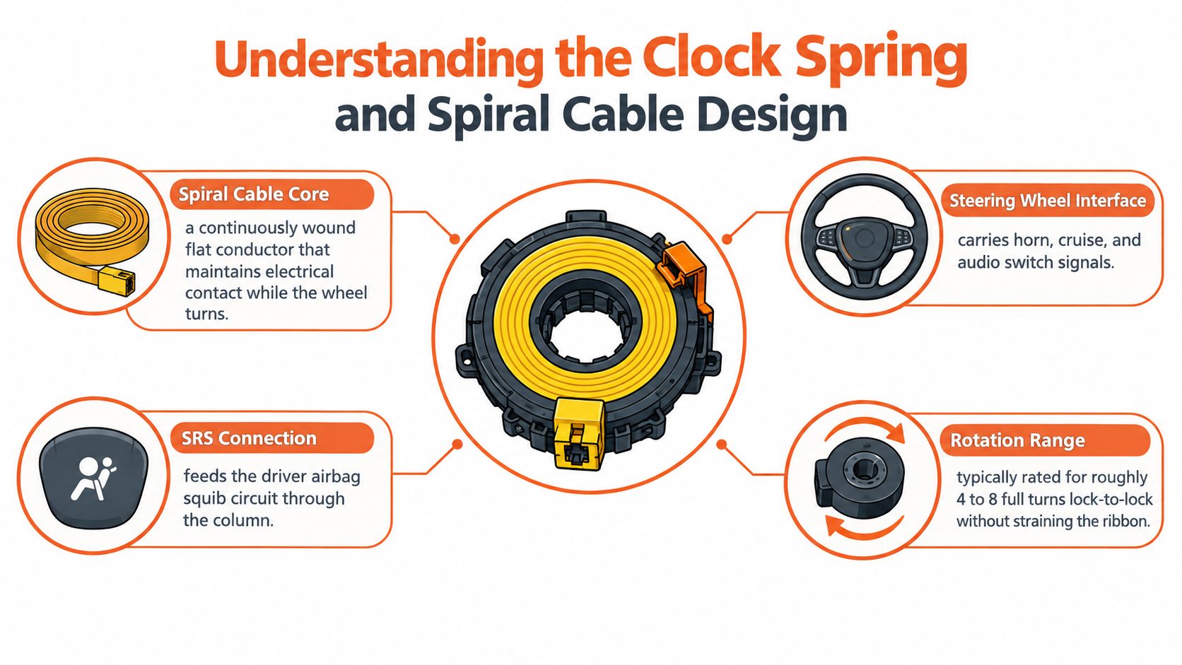
A clock spring, also called a spiral cable or steering-wheel rotary electrical connector, is the link between stationary wiring in the steering column and electrical components attached to the rotating steering wheel. Its circular housing contains a flat ribbon cable wound into a controlled spiral. As you turn the wheel, the ribbon winds and unwinds inside the housing rather than twisting a bundle of ordinary wires.
That arrangement solves a mechanical problem. A normal wire can flex, but repeated twisting through the steering wheel's operating range would eventually fatigue or break it. The clock spring gives the conductor a defined path and a finite travel range, allowing the wheel to rotate while preserving electrical continuity.
What the assembly carries
The driver airbag is the most safety-critical circuit commonly routed through the assembly. The same component can also support the horn and steering-wheel controls, including audio, cruise-control, and information-system switches. In some vehicle designs, the clock spring also mechanically drives a steering-angle sensor, allowing that sensor to interpret steering position and angular velocity from wheel movement.
That combination explains why one failed component can produce several apparently unrelated symptoms. A ribbon circuit may lose continuity to the airbag while another circuit still operates, or a connector problem may affect the steering-wheel buttons without affecting every other function. A useful overview of the surrounding column hardware is available in this guide to what the steering column does.
The technology developed alongside modern steering-column electrical systems. A General Motors steering-column electrical-coupling patent had a priority date of December 17, 1971, and a related patent was published on October 2, 1973. Later “Clock spring” patents filed by Alps Electric included a February 6, 1990 priority filing published in 1991, documenting the move toward dedicated spiral-cable assemblies as driver airbags and multifunction wheels became established technologies. These patent milestones are documented in the US5580259A patent record.
Practical rule: Treat the clock spring as part of the driver-airbag continuity chain, not as a simple harness for convenience buttons.
Recognizing Failure Symptoms and Safety Recalls
A deteriorating clock spring can announce itself through a single function or several at once. The SRS or airbag warning light is the symptom that deserves the most attention, because an open ribbon circuit can disconnect the driver airbag from the restraint-control system. A dead horn, inoperative steering-wheel switches, or intermittent controls can point toward the same assembly, but none of those signs identifies the failed component by itself.
Mechanical noise provides another clue. Popping, clicking, grinding, creaking, or clacking behind the steering wheel can occur when contamination interferes with the internal guide loops or when the ribbon is moving abnormally. Noise is useful evidence, but it still needs to be correlated with fault codes, connector condition, and circuit testing.
What recall documentation shows
NHTSA recall documentation describes several concrete failure mechanisms. In a 2014 Volkswagen recall covering certain 2010–2014 vehicles, including CC, Passat, Golf, GTI, Jetta, and Tiguan models, debris could contaminate the spiral-wound flat cable assembly. The debris could tear the cable, illuminate the airbag warning lamp, and prevent the driver's frontal airbag from deploying in a crash requiring deployment, as described in NHTSA's Volkswagen Jetta recall information.
A separate 2015 NHTSA safety-recall report explained that long hair or fibers could displace internal guide loops. That displacement could create abnormal tension and tear the flat cable, eliminating the electrical connection to the driver airbag. The report is available in NHTSA's recall document.
A later 2022 NHTSA recall attributed failures to dust contamination and increased friction. Reported symptoms included a popping or clicking sound, an inoperative horn, nonfunctional steering-wheel switches, and an illuminated airbag lamp. The pattern matters because it connects physical contamination to both safety and convenience failures.
An airbag warning light after steering-wheel work or a collision isn't a cosmetic warning. Diagnose it before treating the vehicle as repaired.
Diagnosing Clock Spring Faults Versus Other SRS Issues
An illuminated airbag light doesn't automatically mean the clock spring failed. The same warning can result from damaged connectors, wiring faults, an SRS control-module issue, a disturbed seat-belt pretensioner, or incorrect steering-wheel alignment. After a collision, several of those conditions may exist at the same time.
Begin with the vehicle's manufacturer-specific SRS scan data. A generic engine-code reader may not access the restraint module or may provide too little detail to identify the affected circuit. Record the code before clearing anything, because the code's location and wording help determine whether the driver-airbag circuit is involved or whether the fault belongs elsewhere.
A disciplined diagnostic sequence
- Scan the SRS module. Identify whether the code names the driver airbag, a passenger restraint, a seat-belt pretensioner, the steering-angle sensor, or an internal module fault.
- Inspect the disturbed area. Check clock-spring connectors, terminal pins, column wiring, grounds, and any harness that may have been pulled during steering-wheel or column work. Look for partially seated locks, bent terminals, chafing, and impact damage.
- Compare the symptoms. A horn and audio buttons that fail only at certain wheel positions can support a rotational-continuity fault. A code for a passenger airbag or pretensioner points away from the clock spring. Multiple dead circuits may suggest a fuse, power, or ground issue.
- Test according to the service procedure. Circuit continuity and resistance checks must follow the manufacturer's instructions. Never probe an airbag squib circuit with unsuitable test equipment, because the wrong method can create a serious deployment hazard.
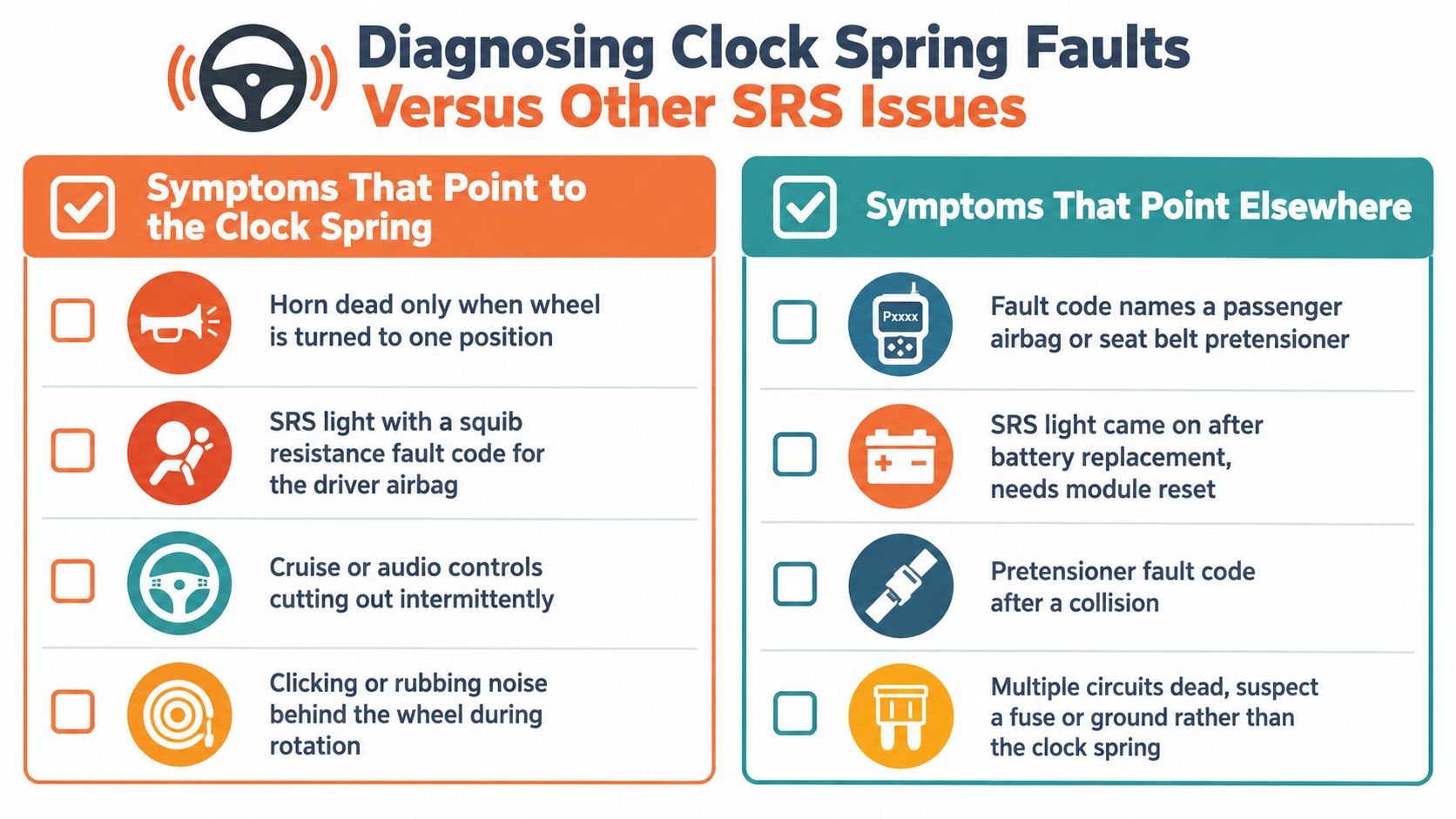
The correct workflow avoids unnecessary parts replacement. A Kia technical bulletin, referenced in this airbag-light diagnostic guide, illustrates why symptoms can be function-specific: one circuit may disable the airbag while the horn or audio controls still work, while a connector-pin problem may affect the controls without impairing the airbag circuit.
The diagnostic video below can help technicians visualize the type of fault-isolation process required:
The Critical Importance of Centering and Installation
A replacement clock spring can fail immediately if it's installed off-center. The ribbon cable has a finite winding range, so the assembly must sit at its specified neutral position when the front wheels and steering wheel are straight ahead. If someone rotates the column while the clock spring is disconnected, the unit may reach its internal stop after installation and tear the ribbon during steering.
Preserve the neutral position
The locking or alignment device supplied by the manufacturer is not packaging. Keep it engaged until the assembly is ready to mount, and don't force the unit past its stop to make the connectors line up. Vehicle procedures differ, so the exact centering method, battery isolation process, and waiting period must come from the service information for that vehicle.
Before installation, technicians should:
- Secure the steering position: Keep the front wheels straight and prevent unnecessary column rotation while the wheel and clock spring are disconnected.
- Match the correct configuration: Confirm the part number, connector layout, steering-angle-sensor arrangement, and vehicle options before fitting the assembly.
- Engage every connector lock: A connector that looks inserted may still have an unsecured secondary lock or a displaced terminal.
- Check the post-installation functions: Verify the SRS indicator, horn, and wheel-mounted controls, then complete steering-angle-sensor calibration if the vehicle requires it.
The danger is mechanical, not merely electronic. An off-center clock spring may appear functional while the vehicle is stationary. The ribbon can tear later when the driver reaches full lock, leaving an open airbag circuit and potentially disabling the horn or controls at the same time.
Installation standard: Center first, connect second, and calibrate only as the vehicle manufacturer specifies.
Steering-column problems can also make the wheel difficult to rotate or release. For a separate mechanical reference, this steering wheel lock stuck guide may help distinguish a lock-related issue from a clock-spring indexing problem. It isn't a substitute for the vehicle's SRS procedure.
Integrating Clock Spring Work into Post-Collision SRS Repair
A collision repair isn't complete when the steering wheel looks straight and the replacement clock spring is bolted in. The impact may also have deployed seat-belt pretensioners, damaged airbags, triggered crash sensors, or stored hard crash data in the SRS control module. The clock spring must be handled as one item in a complete restraint-system restoration.
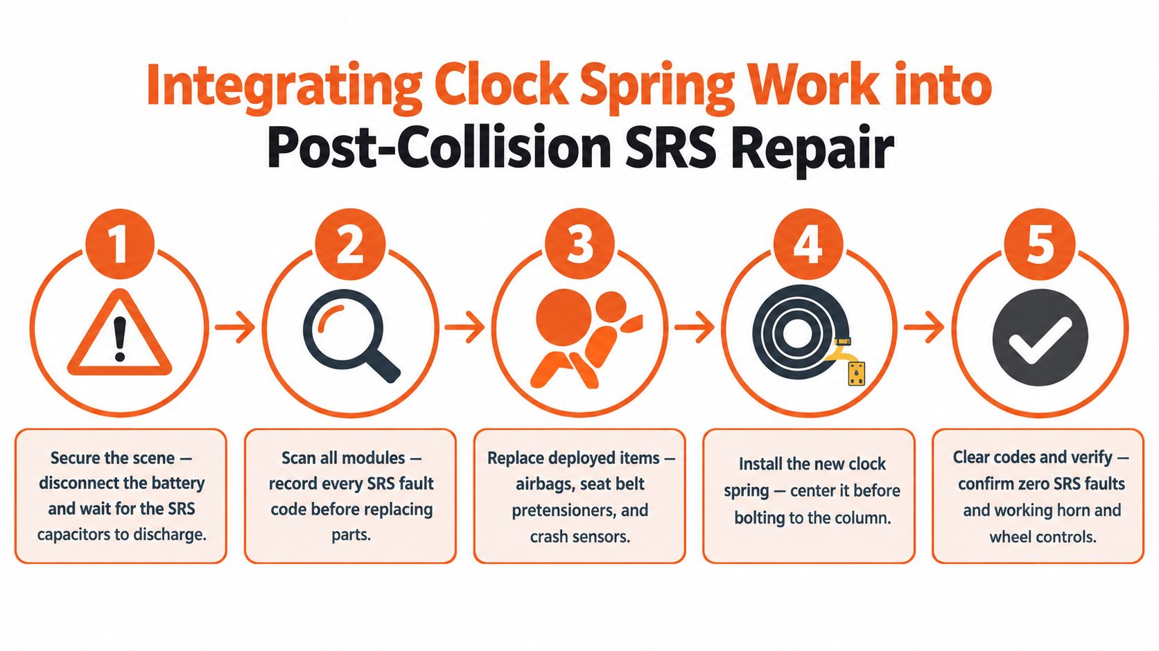
Start with the vehicle electrically isolated according to the manufacturer's instructions, then scan the SRS system before removing parts. Recording the codes provides a baseline and helps prevent a new installation fault from being confused with an original collision fault.
A practical rebuild sequence
- Secure the vehicle: Follow the restraint-system isolation procedure before working around the driver airbag, column, or belt pretensioners.
- Map the damage: Scan all accessible SRS modules and inspect airbags, belts, sensors, wiring, and connectors before ordering parts.
- Restore deployed hardware: Replace damaged airbags and crash sensors as required, and address locked or deployed pretensioners rather than clearing codes alone.
- Install the clock spring correctly: Keep the wheels straight, preserve the alignment lock, and confirm the assembly is centered before the steering wheel is installed.
- Validate the repair: Clear codes only when the underlying faults are corrected, then confirm the SRS lamp behavior and test the horn, switches, and steering-angle system where applicable.
The electronic module deserves separate attention. A restraint-control unit can retain crash data or hard codes after a collision, and a clock-spring replacement won't erase those records. The broader relationship between replacement parts and resettable components is explained in this guide to what happens to an airbag system after a crash.
For owners and rebuilders managing an insurance repair, documenting the damaged SRS components and repair path also matters. A specialist resource on Auto Appraisal Expert claim help can be useful when the visible body damage doesn't reflect the full cost of restoring safety systems.
Common Questions About Clock Spring Safety and Replacement
Can I drive with a bad clock spring?
You shouldn't treat an unresolved SRS warning as safe just because the vehicle starts and steers normally. The horn or steering-wheel controls may continue to work, but a fault in the driver-airbag circuit can mean the restraint system isn't ready to deploy correctly. Arrange professional diagnosis promptly, and avoid using the warning light as a cosmetic indicator.
Does an airbag light prove the clock spring failed?
No. The light only confirms that the SRS module detected a fault. Connector damage, wiring problems, an incorrect steering-wheel position, a pretensioner fault, or a control-module issue can produce similar warnings. The right answer comes from manufacturer-specific codes, inspection, and approved circuit tests.
Is a used clock spring automatically safe?
No. Matching the appearance or connector count isn't enough. Confirm the vehicle-specific part number, circuit layout, index position, steering-angle-sensor configuration, and condition of the assembly. A used unit may have been rotated while removed, damaged in a collision, or affected by a prior airbag deployment.
What should be checked after replacement?
The wheels should be straight, the clock spring should be locked or centered according to the service procedure, and every connector should be fully engaged. The technician should then verify the SRS indicator, horn, steering-wheel switches, and steering-angle-sensor operation where fitted. If the SRS lamp remains illuminated, scan again rather than repeatedly swapping components.
Can a clock spring affect steering?
The clock spring normally preserves electrical continuity and doesn't provide the mechanical steering force. However, an incorrectly installed or damaged assembly can create rubbing or clicking, and the steering-angle sensor integrated into some designs may affect related vehicle systems. Mechanical resistance, a locked wheel, or a steering fault needs separate diagnosis.
The central lesson is simple: a clock spring is a precision safety component with limited rotational travel. Diagnose the circuit before replacing the part, center the assembly before installation, and confirm the complete SRS system afterward. Guessing can leave the driver airbag disconnected or destroy a new component on the first full turn.
Seat Belt Repair provides mail-in repair for locked or deployed seat-belt pretensioners, damaged webbing, and SRS airbag control modules with crash data or hard codes. If your clock-spring diagnosis is part of a wider collision repair, visit Seat Belt Repair for OEM-based component service and guidance on sending the correct parts for testing and repair.

Leave a comment
This site is protected by hCaptcha and the hCaptcha Privacy Policy and Terms of Service apply.