
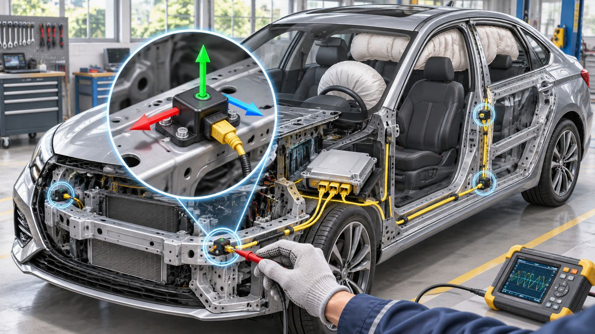
A car can have new airbags and still greet you with an airbag warning light. Or you may be scanning a salvage vehicle and find a fault naming the multi-axis acceleration sensor. Neither clue, by itself, proves the sensor needs replacing. The light can stay on because the restraint control module has stored a crash event, a belt pretensioner has fired, or a circuit is still open.
Think of the sensor as the module's direction witness. It reports how the vehicle moved; the control module uses that information, together with other inputs, to decide which restraints to command. The useful job in the bay is to match the reported axis and location to the damage, then test the circuit and the parts that acted.
Table of Contents
- Why the Airbag Module Trusts This Sensor
- Which Axis Flags Which Crash
- Outputs Ranges and Mounting That Matter
- How to Test the Sensor Before You Replace It
- Frontal Side and Rollover Examples
- Mistakes That Leave the Airbag Light On
- Repair the Belt and Reset the Module
Why the Airbag Module Trusts This Sensor
A multi-axis acceleration sensor is a MEMS device that measures straight-line acceleration along two or three perpendicular axes. In plain terms, it tells the supplemental restraint system whether the vehicle was shoved front to back, side to side, or up and down. That directional report helps the module distinguish a frontal crash from a side impact, a curb strike, or vertical motion that may be relevant to rollover logic.
A single-axis sensor watches only one direction. A yaw or roll-rate sensor reports rotation instead of straight-line acceleration; it may be mounted near the accelerometer, but it measures a different kind of movement. The module can use these signals together, but they aren't interchangeable.
The sensor's place in the system
The module may contain a central sensing element or safing sensor, with additional satellite sensors installed around the vehicle. Depending on the design, a satellite may sit in the front structure, a door, a B-pillar, or the center tunnel. The exact layout is vehicle-specific, so use the service information and wiring diagram rather than assuming every car puts the sensors in the same places.
A central sensor reads the vehicle's movement through the cabin. A remote sensor can register a local impact sooner or more directly. The module compares those inputs with its deployment logic before commanding a restraint. A safing sensor provides a separate confirmation; it isn't a substitute for the directional sensing channels.
Bench rule: Treat the fault description as a place to start looking, not an order to install a part.
A warning that remains after repairs may point to stored crash data or an unresolved circuit fault, not a failed accelerometer. A restraint control module overview can help clarify the module's role in the wider system. By the end of the diagnosis, you should be able to relate an axis to the restraint path, separate a bad sensor from stored event data, and recognize when a belt or module still needs repair.
Which Axis Flags Which Crash
| Channel | What it measures | Event it helps flag | Restraint path |
|---|---|---|---|
| Longitudinal X | Front-to-rear acceleration | Frontal and offset crash | Frontal airbags and pretensioners |
| Lateral Y | Side-to-side acceleration | Side impact or pole | Side airbag and curtain on that side |
| Vertical Z | Up-and-down acceleration | Rollover assist, some underrides | Curtain or rollover logic with roll rate |
| Front satellite | Early pulse in the front structure | Frontal crash before the cabin feels it | Earlier frontal and pretensioner decision |
| Door or B-pillar satellite | Local side-structure pulse | Side or pole impact | That side's bag and curtain |
| Safing or arming sensor | A second confirming acceleration | Real crash versus abuse or noise | Enables deployment; does not fire alone |
Read the axis against the damage
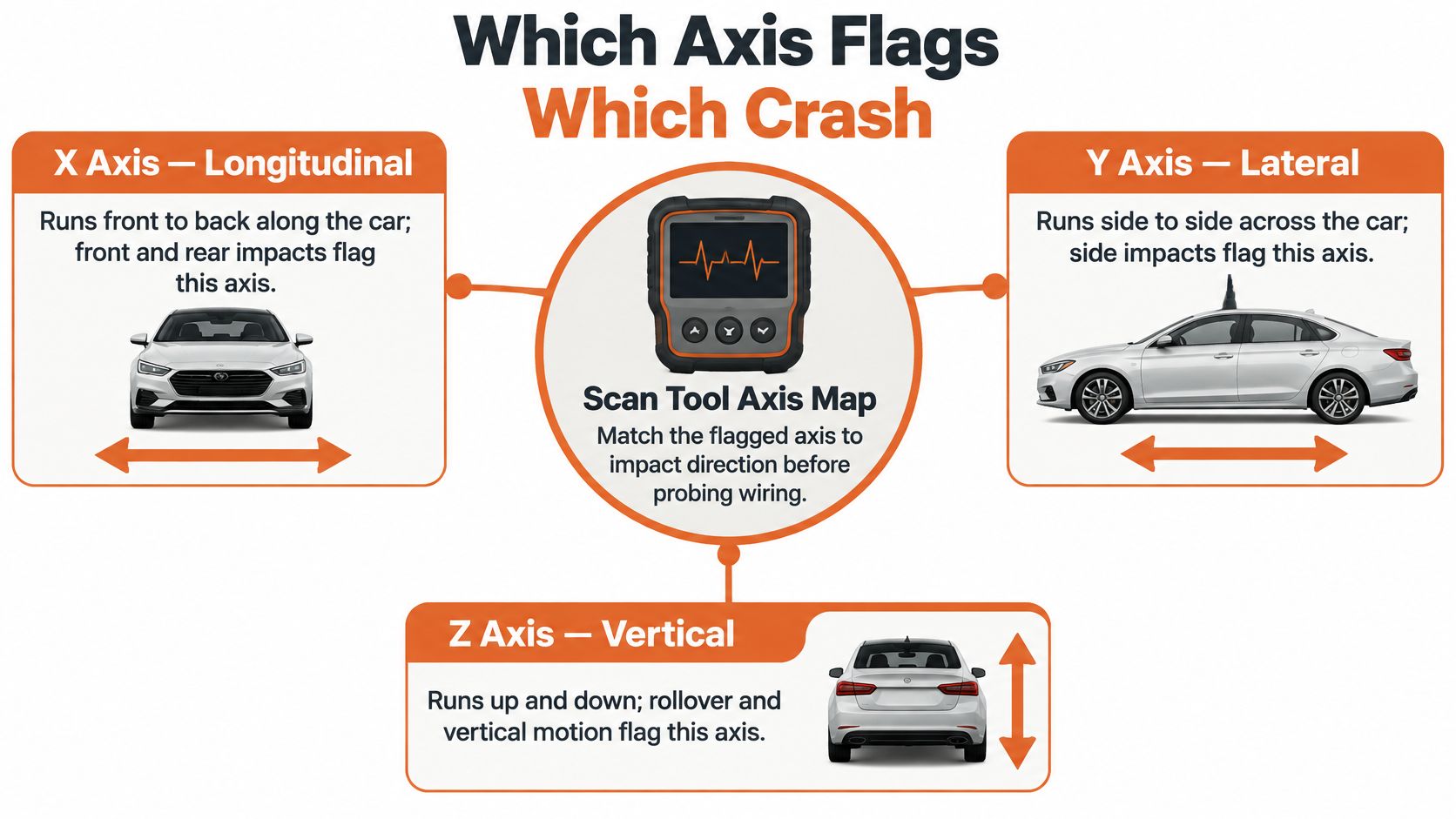
X runs along the car, from front to rear. A frontal or offset hit loads that channel, and the module may use the information for frontal airbags and pretensioners. A front satellite can register the pulse before it reaches the cabin sensor, giving the module a local view of what happened at the front structure.
Y runs across the car. A side impact or pole strike loads the lateral channel. The door or B-pillar satellite can help the module identify which side took the hit, supporting the decision for that side's bag and curtain. If the damage is on the driver's side but the scan points to the passenger side, inspect the sensor location, mounting, and wiring before ordering parts.
Z runs vertically. The module may use vertical motion with roll-rate information for rollover-related logic. A vertical jolt alone doesn't make a side satellite unnecessary, and a Z-axis clue should prompt inspection of the wider rollover context rather than a guess at a single failed part.
The safing channel adds confirmation so one sharp jolt, such as a door slam or a rough crossing, doesn't automatically command deployment. It doesn't decide the direction on its own.
A code that names an axis or satellite tells you where to compare the scan result with the vehicle's structure. It doesn't prove the named sensor has failed. Start at the affected corner or impact path and look for physical damage, a displaced mount, a damaged connector, or wiring trouble.
Outputs Ranges and Mounting That Matter
Inside a MEMS accelerometer, a tiny proof mass shifts as the vehicle accelerates. Capacitive sensing detects that movement, and the electronics turn it into a signal the restraint module can interpret. The package, electronics, and calibration are designed for the vehicle's crash-sensing job. A phone's motion sensor or a general-purpose development board isn't a valid substitute.
The important difference isn't just how the reading is displayed. The airbag module evaluates an event as a changing pulse and uses its own deployment logic. A peak value on a screen doesn't tell you, by itself, whether the module should fire a restraint.
What reaches the module
| Output | What leaves the sensor | What a scan tool may show | Shop limit |
|---|---|---|---|
| Analog voltage | A bias voltage that moves with g | Live g or voltage if the OEM PID exists | A meter checks bias and wiring, not the crash algorithm |
| SPI or similar digital | Clocked acceleration words | Internal module data, rarely at the connector | Don't probe the bus with a test light |
| PSI5 current | Current levels that encode data and ID | Sensor ID, signal faults, implausible values | A wrong ID after a swap can set a code on a good part |
| Module-internal MEMS | No external sensor connector | Plausibility and crash-record data | Replacing the sensor means replacing or resetting the module |
An analog channel may have a resting bias specified by the manufacturer. If the service information provides a test procedure, compare the reading with that procedure. A rail-stuck signal or a channel that fails to respond as specified can indicate a sensor or wiring fault, but check power, ground, and connector condition before condemning the part. Digital outputs need the right scan data and test method; a test light can damage a communication circuit.
Mounting is part of the measurement
The sensor's orientation tells the module which physical direction corresponds to X, Y, and Z. Its connector, locating tabs, and bracket help establish that orientation. Install it backward, fasten it to a bent bracket, or mount it on a repaired structure that no longer sits in the correct plane, and a real vehicle movement may reach the sensor on the wrong axis.
Don't use a generic “zero” or relearn routine to compensate for a badly mounted sensor. First fit the part in its original orientation and torque it as specified. Then perform any calibration the vehicle's service information requires. Calibration can't straighten a bracket or correct a sensor that's been clocked incorrectly.
How to Test the Sensor Before You Replace It
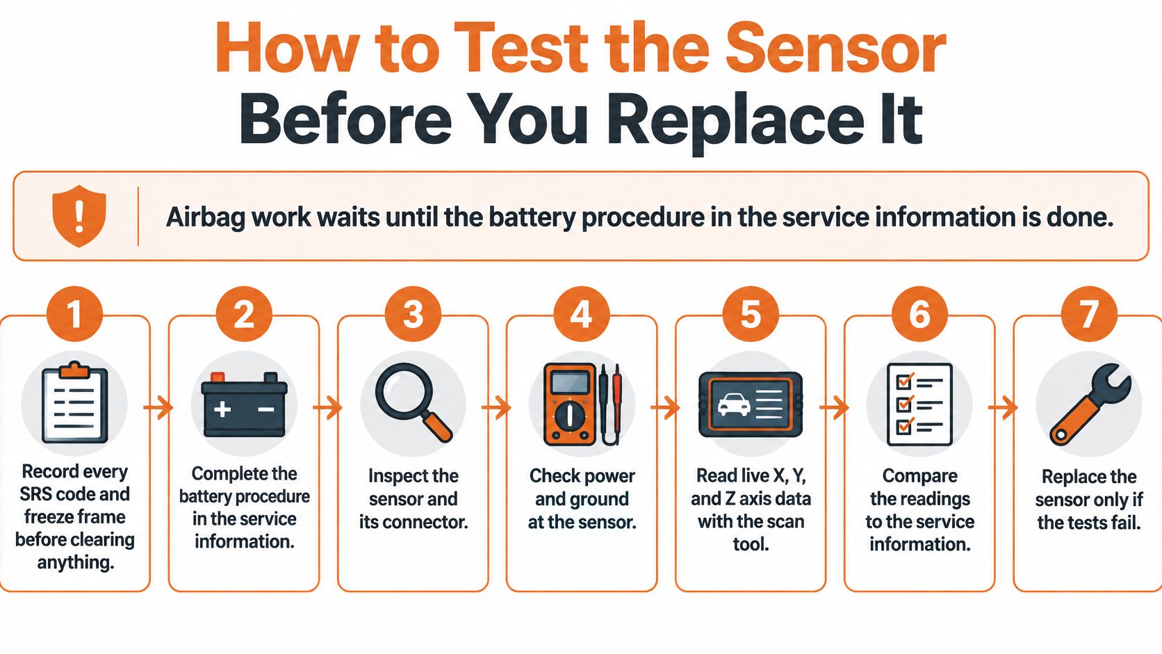
Airbag work starts only after you've followed the battery-disconnection procedure in the vehicle's service information. Don't shake a connected sensor with the system active or try to provoke a deployment. The diagnosis should be based on scan data, circuit checks, and the actual impact path.
Work through the fault in order
- Record the SRS codes and freeze-frame information. Note which axis or satellite the tool identifies before clearing anything. A description such as “implausible signal” is not the same as “crash data stored.”
- Compare the code with the collision damage. Frontal damage makes an X-channel or front-satellite issue worth checking. Side damage points you toward the Y channel, the affected side's satellite, and that side's wiring. A harsh bump with no deployment still needs diagnosis, but it isn't automatically a fired-system repair.
- Inspect the mount and harness. Look for spread or pushed-back pins, corrosion, strained wiring, a bent bracket, or a sensor fastened out of plane on a repaired rail. Check the connector lock and the part number before blaming the sensor itself.
- Check power and ground. Use the wiring diagram and the manufacturer's test procedure. A sensor can report incorrectly because it isn't receiving a good supply or return path.
- Read live data if the OEM tool provides it. Compare the channels at rest with the specified values. Only tilt a removed-but-still-plugged sensor if the service procedure permits that test. A channel that stays at its electrical limit suggests a fault; readings that change in an unexpected direction can point to incorrect mounting.
- Test a fired pretensioner only after isolating it. A properly working pretensioner reads 2 to 3 ohms when measured with a multimeter in an OHM test. Follow the vehicle's safety procedure and use the correct method for the squib circuit. An open or near-short in the isolated pretensioner circuit directs attention to the belt assembly, not automatically to the accelerometer.
- Clear codes only after the repair. If a code returns as crash data stored while live acceleration readings look normal, the module memory may be holding the event. A new sensor won't erase that record.
The SRS scan tool guide can help with the distinction between reading a fault and repairing what caused it.
| Clue | Usually means | Do not assume | Next check |
|---|---|---|---|
| Implausible or stuck-g code | Channel not moving or biased off scale | The module algorithm failed | Live data, mounting plane, power and ground |
| Satellite open or wrong ID | Connector, harness, or wrong part | The central sensor is bad | Pins, ID, and that corner of the car |
| Crash data stored, live g normal | The event was recorded | A new sensor will turn the light off | Module reset after bags and belts are addressed |
| Intermittent after body work | Harness or bracket strain | The MEMS died in the crash | Wiggle test and mount alignment |
| Pretensioner open after a fire | Squib circuit not 2 to 3 ohms | The acceleration sensor caused the open | Belt stage and pretensioner, then the module |
| Light after a harsh bump, no deployment | Self-test or a brief fault | Bags must be replaced | Codes and live data before any parts |
An SRS diagnostic walk-through is useful for the scan sequence, but follow the service information for the specific vehicle. This video also shows the kind of scan-tool work involved:
Frontal Side and Rollover Examples
Frontal impact
Say a car has frontal damage, intact-looking airbags, and a driver's belt that won't retract. The front satellite may have registered the pulse at the front structure, while the X channel in the cabin supports the frontal event decision. If the pretensioner fired, the belt can lock even when the airbag didn't deploy. Replacing the acceleration sensor won't free that reel.
Inspect the front rails and the satellite mount, then diagnose the belt and module separately. Connector count can help identify a belt's stage, but use the vehicle's parts information to confirm the correct replacement or repair.
Side impact
A pole strike on the driver's side points you toward the door or B-pillar satellite and the Y channel. The restraint path to inspect is the driver's-side bag and curtain, along with the door structure and the wiring at that location. If a passenger-side sensor code appears instead, check for a displaced or incorrectly installed component before ordering every airbag and satellite.
A side-impact decision is local as well as directional. A sensor on the wrong side, or one installed in the wrong orientation after body work, can make a sound part report a misleading signal.
Rollover or vertical event
A car that rolls into a ditch presents a different pattern from one that gets a sharp vertical jolt crossing rough pavement. The module may combine Z-axis acceleration with roll-rate information when evaluating rollover-related curtain deployment. Inspect the roof and the roll-related sensors, then compare the recorded event with the vehicle's damage rather than treating any vertical jolt as a rollover.
Seat belts can have multiple stages, and a fired stage still needs attention even if the acceleration sensor now reads normally. Seat Belt Repair services single-stage, dual-stage, and triple-stage belts, including units with tensioners locked or deployed after an accident.
For a Hyundai that retains an SRS warning after collision repairs, Hyundai Airbag Module Reset – All Models | SRS Airbag Light Reset & Crash Data Removal is a module-reset service, not a sensor replacement. Stored crash data and damaged restraint components still need to be distinguished and addressed as separate repair items.
Mistakes That Leave the Airbag Light On
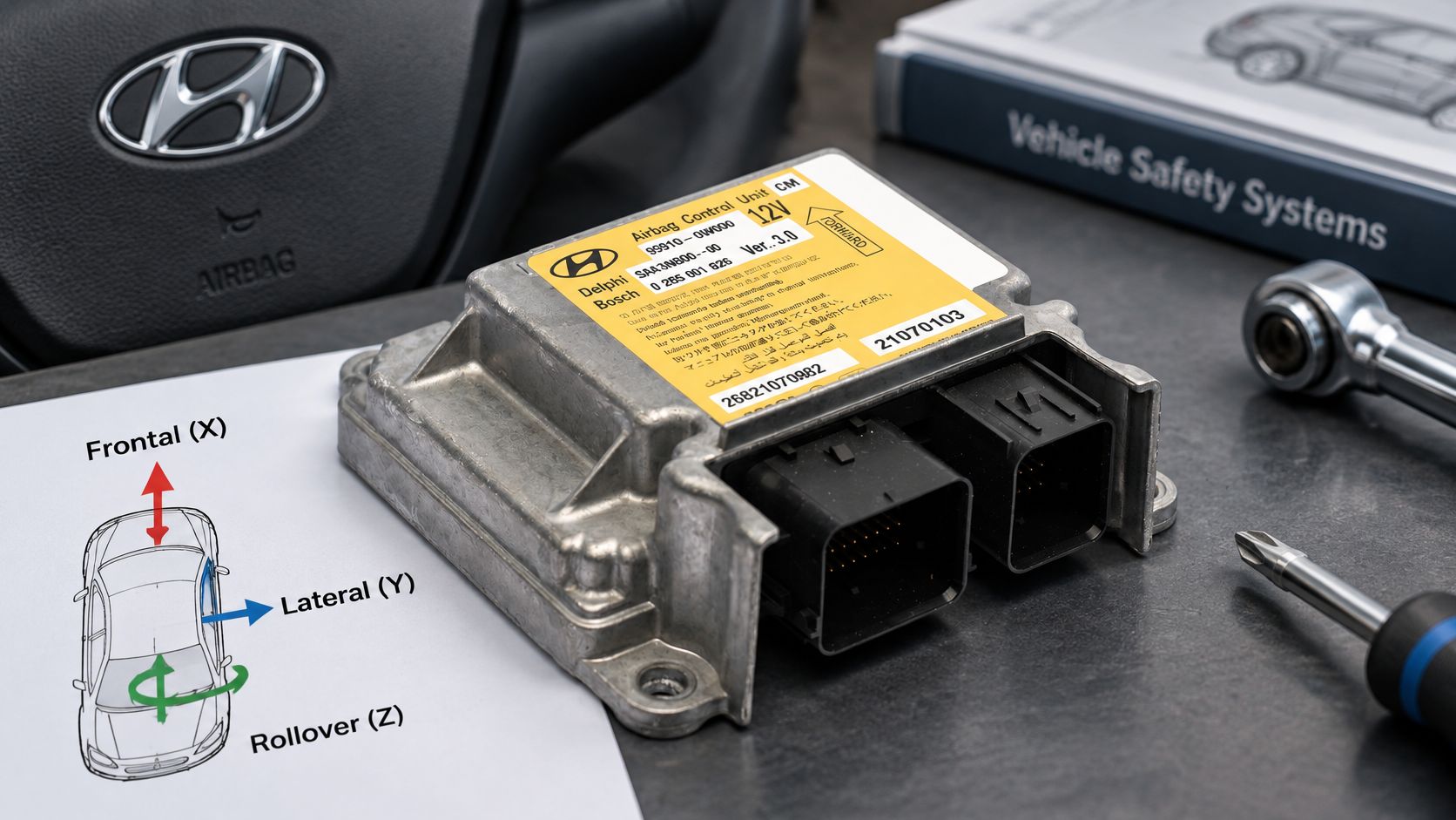
A replacement sensor cannot correct a restraint fault because the collision was severe. The module may have recorded a valid event while the accelerometer still works. Read the fault codes and live data before ordering parts, and distinguish a sensor fault from an event record, an open squib circuit, or a belt fault.
Don't swap parts to test a theory
A used module can bring a stored event or a configuration mismatch. On a scan tool, check whether the reported faults concern the module, sensor identification, or a restraint circuit, then compare them with the vehicle's configuration. Clearing ordinary codes does not necessarily remove stored crash data, and replacing a module without diagnosing the existing faults can leave the warning unresolved.
Moving a left satellite to the right side may create an identification or orientation problem. A sensor turned around on a repaired bracket can feed the module movement along the wrong channel. Body filler, shifted supports, and loose mounts can also affect the signal reaching the sensor. Confirm the part location and mounting position before condemning a component.
A phone app or tap test cannot verify the vehicle's deployment logic, sensor identification, or mounting geometry. A parts listing that calls a component a “G-sensor” or “yaw sensor” does not prove it is interchangeable. One measures acceleration; another may measure rotation.
Don't replace every restraint you can see and leave the part that still holds the fault.
New airbags do not confirm that every restraint fault is resolved. A deployed or locked pretensioner and a module with stored crash data are separate issues to identify from the sensor's condition. For a Volkswagen, the VW Volkswagen Airbag Module Reset – All Models | SRS Airbag Light Reset & Crash Data Removal is described as a module-reset service, not a sensor repair. Inspect the scan results and the restraint components before deciding what needs attention.
Ask which channel reported the event, which restraint path the module commanded, and which fault remains current. That makes the accelerometer a direction witness in diagnosis, not a part to replace by habit.
Repair the Belt and Reset the Module
If the sensor's live data and mounting check out, stop buying accelerometers. A belt that locked, deployed, or won't retract needs its pretensioner and fired stage addressed. Cut, torn, or otherwise damaged webbing needs repair or replacement as a belt component, not an electronic reset.
When the module has stored crash data, clearing ordinary codes alone may leave the warning on. A reset can be added to a belt order, and resetting the module at the same time is recommended when it recorded the crash. Seat Belt Repair offers mail-in seat-belt service and airbag module reset; the module is mailed in, and the local shop or owner handles installation. Read about seat-belt pretensioners and why they need repair before treating a locked belt as a sensor problem.
Before sending components, identify the belt stage using the vehicle information and connector count, and send the fired belt and module when both need service. Replace a satellite only when the diagnosis shows it has failed. After the parts return, install the module and belts correctly, torque sensors in their original orientation, and confirm the system with the appropriate scan tool. That sequence keeps the multi-axis acceleration sensor in its proper role: a direction witness, not a part replaced by habit.
Seat Belt Repair offers mail-in pretensioner repair and SRS airbag module reset, so the belt and stored crash data can be addressed as separate parts of the same post-collision repair. If your scan points to an axis but the light remains on, visit Seat Belt Repair to review the available services.


Leave a comment
This site is protected by hCaptcha and the hCaptcha Privacy Policy and Terms of Service apply.